Get LiveSPICE
LiveSPICE releases are distributed from the GitHub releases page. Note the following requirements:
- LiveSPICE is a Windows application.
- An audio input/output device is required, a device supporting ASIO is recommended.
- A desktop computer with a recent CPU is recommended for live simulation.
- Requires the Microsoft .NET 6.0 runtime.
Getting Started
Here are some resources in the getting started guide to help you start using LiveSPICE:
- Installation: Installing LiveSPICE.
- Audio configuration: Configuring your audio device.
- Tutorial: Simulate an RC low-pass filter.
Examples
Check out some examples of interesting, real circuits LiveSPICE can simulate in real-time:
About
Overview
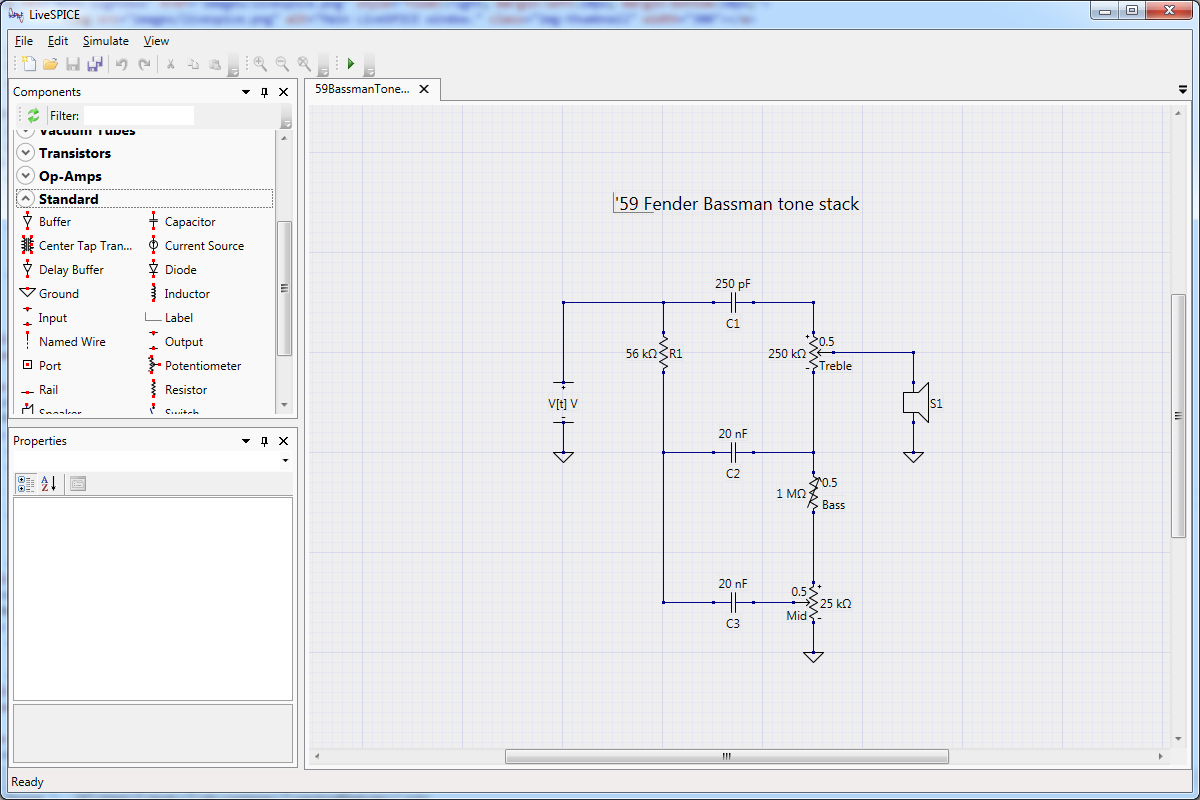
The main LiveSPICE application window for creating and editing circuit schematics.
LiveSPICE is a SPICE-like circuit simulation tool for processing live audio signals. The motivation for developing LiveSPICE is to help prototype guitar effects and amplifiers, without requiring constructing a physical circuit or waiting for an offline simulation to run to try it out. With LiveSPICE, you can design the circuit in an easy to use visual schematic editor, and simulate it using your real audio device as an input signal and your speakers as the output.
Transient simulation of circuits is an extremely computationally intensive task, making it difficult to perform in real time. In addition, circuit simulation is a difficult problem to parallelize, meaning that most of the computer power improvements in recent years are not useful to speed up circuit simulation. In order to deliver real time, low latency transient simulations for audio signals, LiveSPICE is somewhat unique among circuit simulators in the following ways:
- LiveSPICE relies heavily on a custom Computer Algebra System (CAS) to perform circuit analysis. This allows LiveSPICE to evaluate and simplify some of the mathematical operations required to simulate the circuit before simulation begins, minimizing the work required during simulation.
- LiveSPICE Just-In-Time (JIT) compiles a custom simulation program for the particular circuit being simulated. This enables LiveSPICE to separate most of the logic for a simulation for evaluation as a preprocessing step, instead of evaluating it during simulation.
- LiveSPICE uses simpler component models than most circuit simulators will use for many components, such as transistors and diodes. The simpler models are easier to evaluate quickly, helping the simulation to run in real time. However, the simpler models are less accurate and may not replicate the sound of the real circuit as well as a more advanced simulation would.
Despite these measures, there will always be a limit to the complexity of the circuits that can be simulated in real time. More powerful computers will be able to simulate larger and more complex circuits before running into limitations with simulation performance.
LiveSPICE is a hobby project with no particular goal besides making a tool that is fun to use. It is an open source project hosted on GitHub. If you would like to contribute, take a look at the open issues and send a pull request!
Acknowledgements
- Mike Oliphant contributed the VST plugin and related improvements, as well as the demos of the simulations on this page.
Features
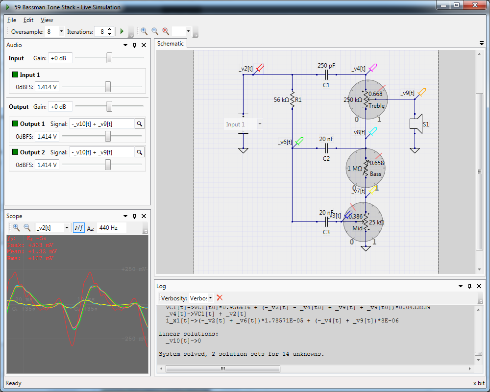
Fender Bassman 5F6-A tone stack controls available during simulation.
The obligatory bullet point feature list:
- Real time, low latency simulations of circuits for live audio signals.
- Easy to use visual circuit schematic editor. The interfaces of many circuit schematic editors are easily mistaken for a torture device. If you feel that way about LiveSPICE, I'd love to know how it can be improved!
- VST plugin enables using your circuits as part of a larger DAW workflow.
- Small but growing library of component and part models, including op-amps, transistors, vacuum tubes, transformers, and more. Custom components can easily be added by simply saving them in the library.
- Support for a subset of SPICE model types (D, NPN, PNP, NJF, PJF) enables utilization of existing SPICE component libraries.
- Supports ASIO audio devices for ultra low latency audio processing.
- Dynamically adjust control components such as potentiometers and variable resistors during simulation.
Coming Soon
Planned future features and improvements but not yet implemented:
- (Possibly limited) interoperability with SPICE netlists.
- Better numerical methods to help simulations of certain types of circuits (those with extreme gain, such as some Darlington transistor circuits).
- Major optimizations to the circuit simulation remain. This should enable better component models and larger and more complex circuits to be simulated in real time.
Examples
Here are some examples of what LiveSPICE is currently capable of simulating. The examples include audio recordings processed using the LiveSPICE VST plugin on clean guitar samples. Other processing, such as amp or speaker cabinets, are applied to both the clean and processed examples.
Some notes about the performance data:
- Performance is reported as the rate of processing by the simulation; if the processing sample rate is greater than the audio sample rate, the simulation can run in real time.
- Factors of real time performance correspond to an audio sample rate of 44.1 kHz.
- Not all simulations require the same oversampling rate to achieve real time performance. The oversampling factor was adjusted from the default of 8x to enable real time simulation as necessary.
- All of the reported performance data is measured on an AND Ryzen 7 5800X.
- There are many variables when measuring performance. Your milage may vary.
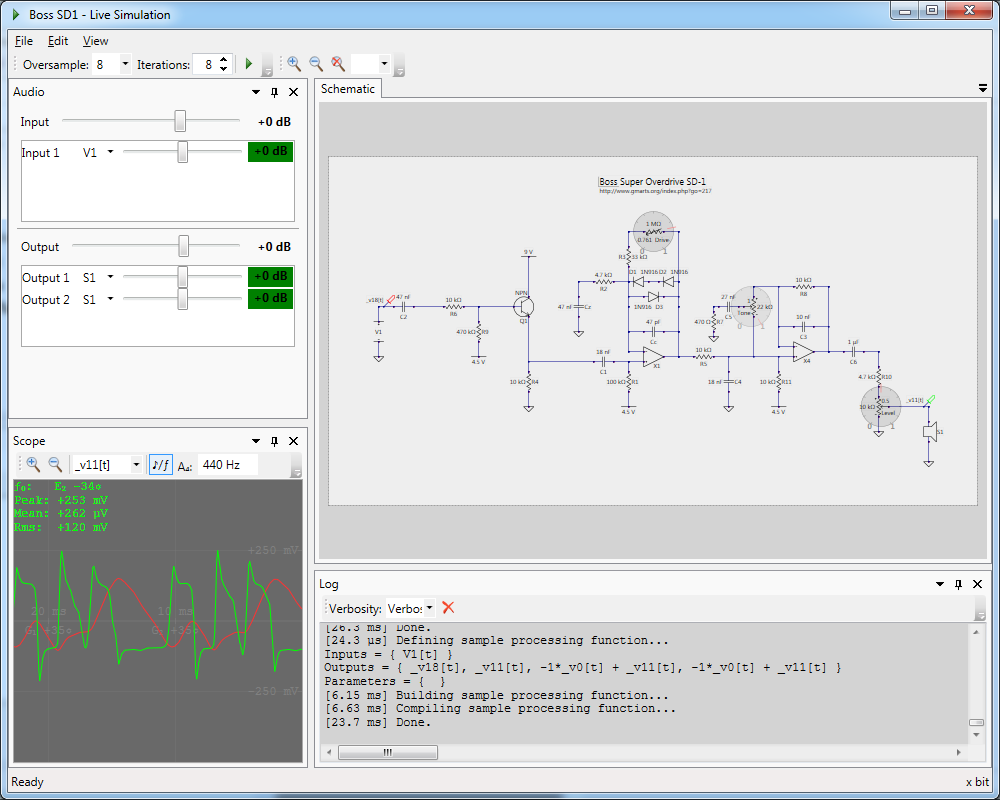
Boss SD-1 "Super Overdrive" guitar pedal.
Recorded into a clean amplifier simulation with a Marshall 1960 cabinet impulse response.
This simulation runs at 392 kHz with an 8x oversampling factor (8.9x real time).
Circuit schematic from GM Arts.
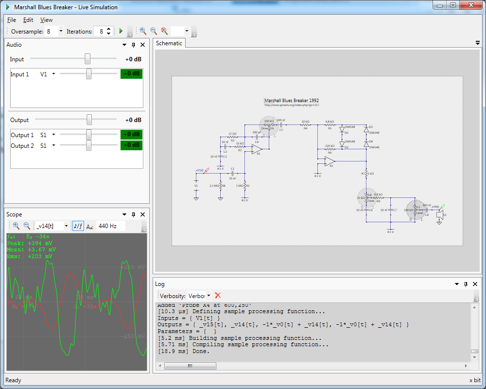
Marshall "Blues Breaker" guitar pedal.
Recorded into a clean amplifier simulation with a Fender Tweed Champ cabinet impulse response.
This simulation runs at 329 kHz with an 8x oversampling factor (7.46x real time).
Circuit schematic from GM Arts.
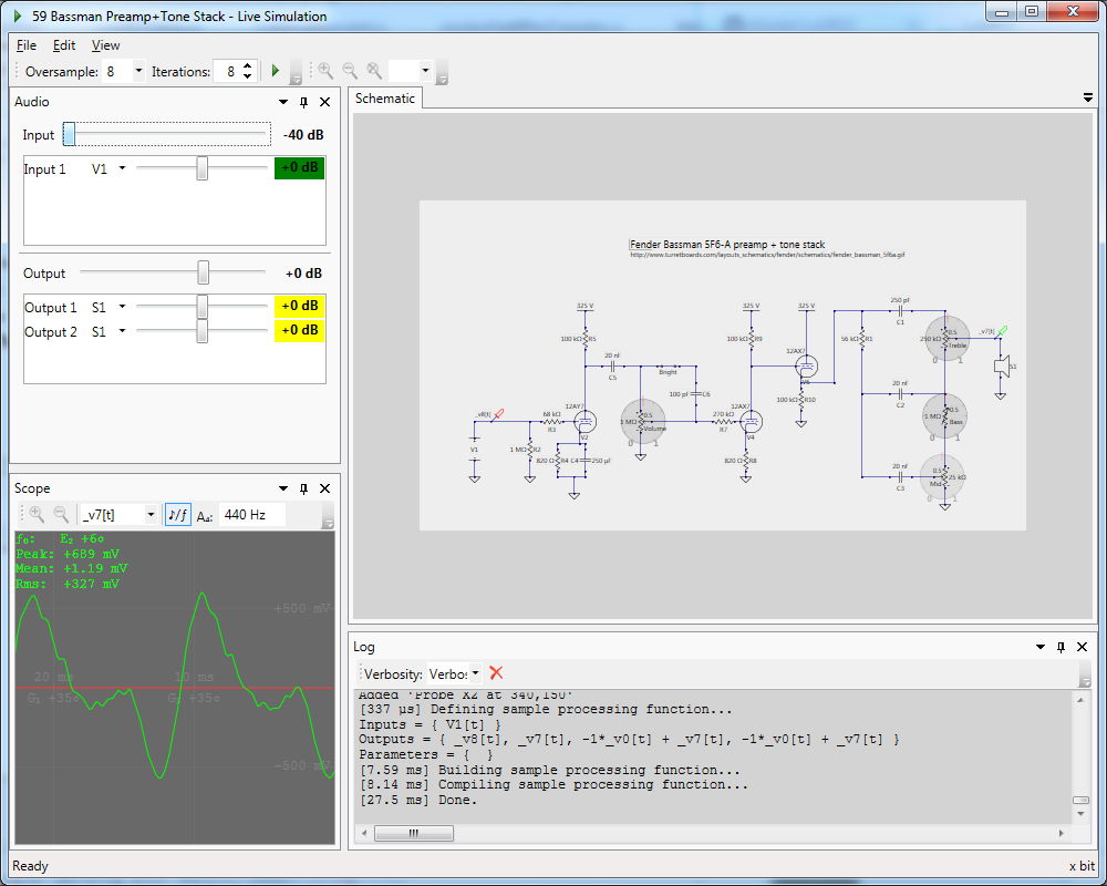
Fender Bassman 5F6-A preamp.
Recorded into a Fender Tweed Champ cabinet impulse response.
This simulation runs at 120 kHz with an 8x oversampling factor (2.73x real time).
Circuit schematic from Watts Tube Audio.
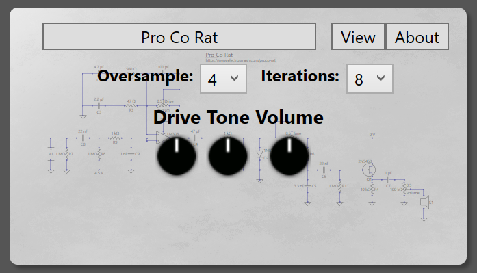
ProCo Rat distortion pedal in VST plugin
Recorded into a clean amplifier simulation with a Marshall Plexi 4x12 cabinet impulse response.
This simulation runs at 94.8 kHz with an 8x oversampling factor (2.15x real time).
Circuit described and analyzed at electrosmash.com.
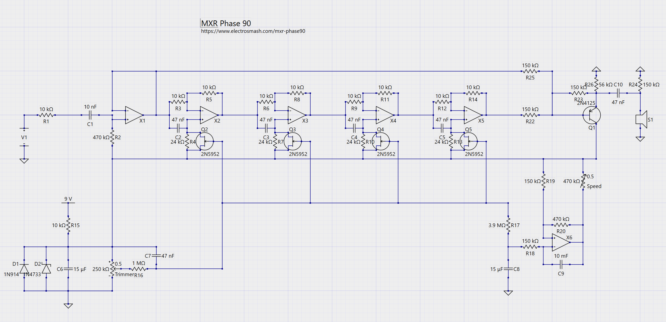
MXR Phase 90 guitar pedal
This simulation runs at 108 kHz with a 2x oversampling factor (2.45x real time). This is a challenging circuit to run in real time, containing many non-linear components. In this case, a high oversampling factor is probably unnecessary because this circuit does not produce significant high frequency harmonics like a distorting or saturating circuit.
Circuit described and analyzed at electrosmash.com.
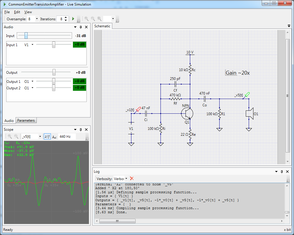
A basic transistor amplifier stage.
This circuit is a building block of many transistor amplifiers.
This simulation runs at 880 kHz with an 8x oversampling factor (19.9x real time).
Circuit described and analyzed in David Yeh's Dissertation (section 5.3).
Video demos
Walkthrough and demo customizing the JCM800 by @Rohbemusic
Fender Deluxe Reverb demo by @adriangas_
Documentation
Getting started guide
Installation
Prerequisites
- Microsoft .NET 6.0 runtime
- ASIO4ALL is recommended if you do not have an ASIO compatible audio device.
Installing
- Download the current release from GitHub releases.
- Run LiveSPICESetup.exe and follow the instructions on screen.
Configuring your audio device
To configure your audio device, use the menu to select Simulate Audio Configuration.
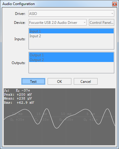
- Choose the driver to use. Prefer ASIO if your device supports it. ASIO4ALL may also be a better choice than the windows audio driver.
- Select your device.
- Select channels to use. Multiple channels may be used simultaneously. A typical scenario is to select one input channel corresponding to a microphone/line in device; and two output channels if the output device is a stereo device.
Use the Test button to ensure your device is working. The test mode captures the signal from the input channels, displays the waveform on the scope, and plays the signal to the output channels.
Check that the signal is visible on the scope to ensure the input channels are configured correctly. LiveSPICE maps the digital signal maximum (0 dB) to 1 V. Therefore, if the peak of the signal is near 1 V, it is likely that your audio system will have clipping issues.
Check that you can hear the signal coming from your output device to ensure the output channels are configured correctly.
Note that the device cannot be reconfigured while the Test button is pressed. Click the Test button again to stop testing and enable reconfiguration of the audio device.
Tutorial: RC low-pass filter
This tutorial will walk through using LiveSPICE to build and simulate a simple passive first-order RC low-pass filter.
This tutorial expects that you have already configured your audio device in LiveSPICE.
For some background on the filter circuit to be simulated, see the low-pass filter article on Wikipedia.
Building the circuit
The first step is to build the circuit we are going to simulate. To begin, select
FileNew to create a new blank schematic.
Adding components
Next, we will begin adding the circuit components. To add a component, find the component in the Component Library and click it. Then, click on the schematic where you want to place an instance of that component. We're going to need the following components, all from the Generic group in the library, to build the filter:
- An Input; the input signal will come from this component, which is an ideal voltage source.
- A Capacitor and a Resistor.
- A Speaker; the output signal is measured as the voltage across this component.
- A Ground.
Arrange the components roughly as follows:
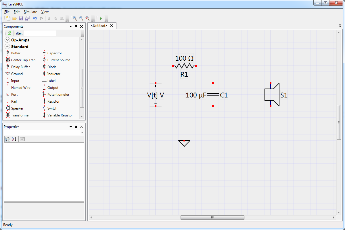
Parts for the RC low-pass filter.
If you need to move the components, select them and then click and drag them to move them. You can also use the arrow keys to rotate and flip the selected components.
Tips
- You can search the component library by typing the name of the component you are looking for in the Filter field at the top of the library.
- Use the arrow keys to rotate and flip components while adding them to the schematic.
Wiring the components
Next, we need to wire the components together. Select the Wire component from the library (or press Ctrl+W). Adding wires is a little different from the rest of the components, to draw a wire between two points, click on one point, and drag to the other point. Draw wires to connect the components as follows:
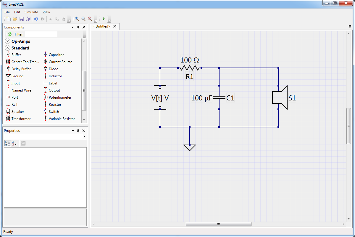
RC low-pass filter wired up.
Tips
- Holding Ctrl will allow you to draw more than one wire without selecting the wire from the library each time.
- A red terminal indicates that the terminal is not connected. Make sure none of the terminals are red before continuing to the next step.
Setting component values
The next step is to edit the values of the resistor and capacitor to build the circuit that we want. Let's build a filter with a cutoff frequency near a D3 (the D string on a guitar), which is 147 Hz. If we use a 1 µF capacitor, we need roughly a 1 kΩ resistor to achieve this. To change the value of the components in the circuit, select a component by clicking it. This will bring up the properties for this component. Edit the Capacitance and Resistance fields of the appropriate components by clicking on them and typing the value.
Tips
- You can use u in place of µ when entering a property value. Similarly, Ohm and Ω are interchangeable.
- While setting incorrect units explicitly for a property will result in an error, unit-less quantities are implicitly interpreted to have the units of the property you are setting.
Running the simulation
Verify that your circuit looks like the following:
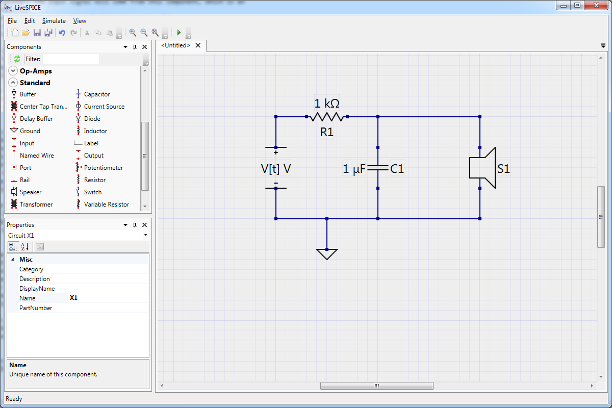
Complete RC low-pass filter.
To run the simulation, select SimulateSimulate on the menu. If you have not yet
configured your audio device, you will be prompted to do so now. The
simulation should now be running!
Click on any of the wires in the schematic to place a Probe. Probes generate signal data from the simulation, which is displayed in the Scope.
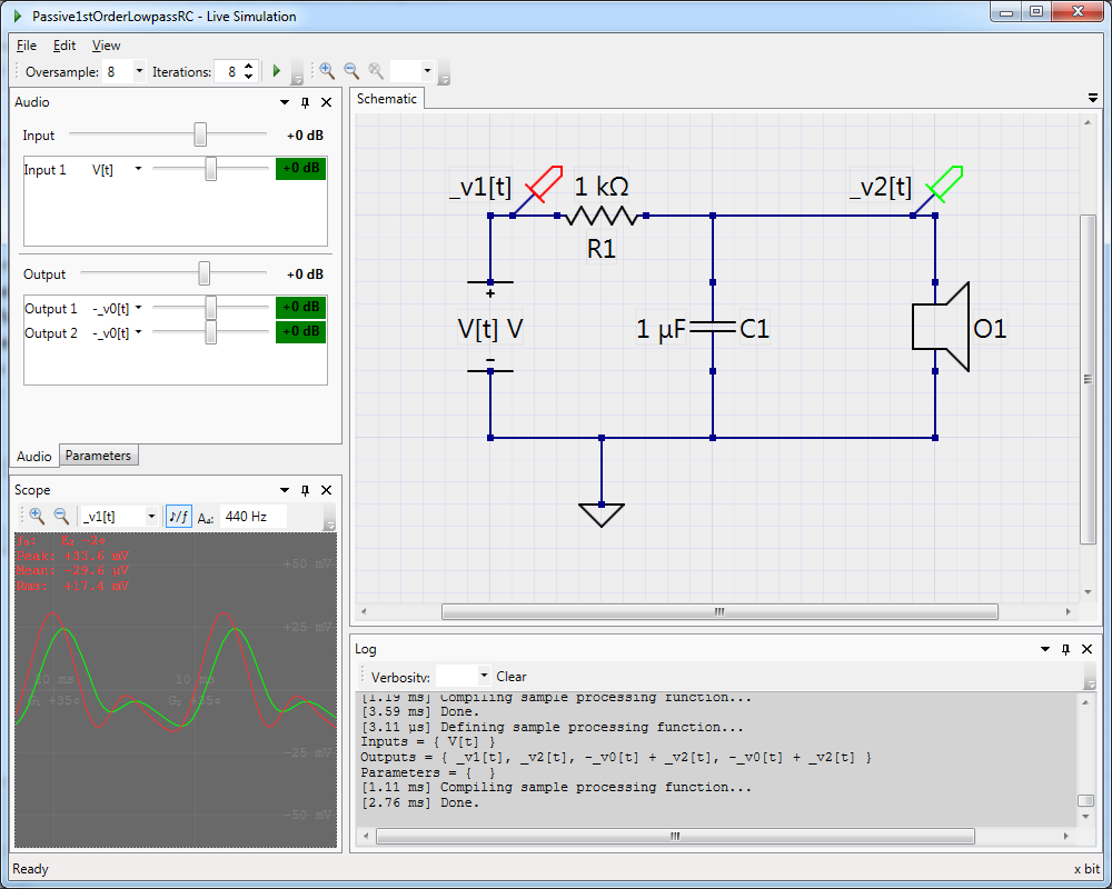
RC low-pass filter simulation.
Using this information, we can verify that the qualitative behavior of the circuit matches our expectations for the circuit we designed:
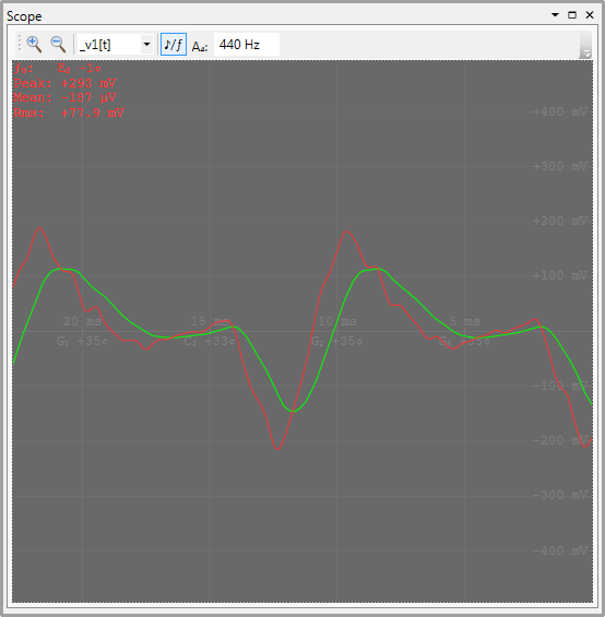
Input (red) and output (green) signals after plucking the low E string (E2, 82 Hz) of a guitar.
Plucking the low-E string of the guitar shows the higher harmonics filtered, and the gain of the circuit near unity.
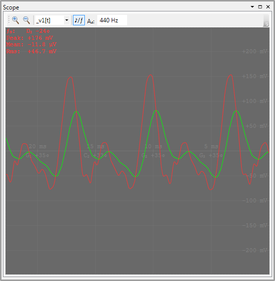
Input (red) and output (green) signals after plucking the D string (D3, 147 Hz) of a guitar.
We selected the corner frequency of the circuit to be the frequency of this note, and we can indeed roughly see the expected gain of -3 dB (1/2).
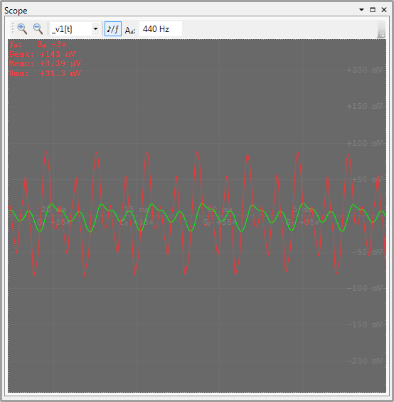
Input (red) and output (green) signals after plucking the high E string (E4, 330 Hz) of a guitar.
Plucking the high-E string shows a gain significantly smaller than unity, as expected.
Tips
- If the signal is too quiet or too loud, use the gain adjustments on the Audio pane to
adjust the amplitude of the signal.
- Adjusting the Input gain or the gain of one of the input channels will adjust the amplitude of the signal before it is processed.
- Adjusting the gain of the Output or one of the output channels will adjust the amplitude of the signals after they are processed.
Running the simulation in a VST host
After verifying the circuit functions as intended, the VST plugin allows the circuit to be used as part of a larger
audio processing workflow implemented in a VST host application. Click
FileSave as... and save the RC low-pass
filter as RC Lowpass.schx in an suitable location.
Launch your DAW/VST host application, and begin or open a project, and add an instance of the LiveSPICEVst plugin to your project or workflow.
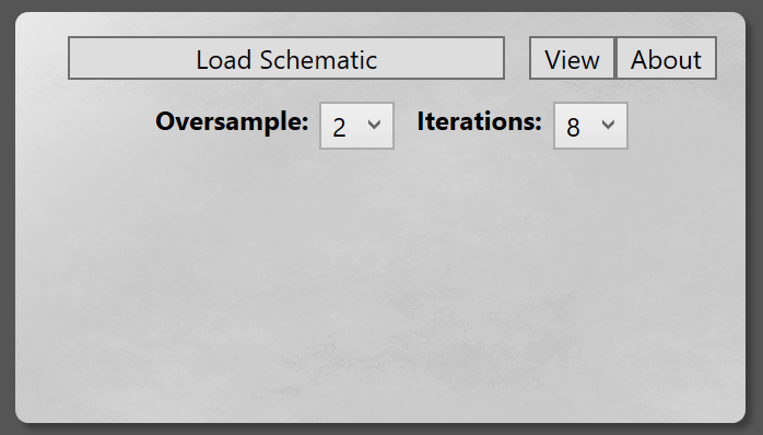
Default state of the VST plugin.
Click the Load Schematic button and find RC Lowpass.schx saved previously. The plugin is now ready to process audio, and should produce similar filtering behavior as it did in LiveSPICE.